Skip to content

555 Timer Boost Converter Circuit Diagram

Circuit Diagram 555 Timer

Boost converter circuit 555 Lm2577 boost converter circuit Boost converter circuit using ic 555 – diy electronics projects

Circuit Diagram 555 Timer

Calculated mosfet switching time does not agree w/ expected results Boost bucker converter circuit diagram Buck boost converter using ltc3440 for an output voltage of 3.3 volts.

555 timer circuit diagram tutorial

555 timer boost converter circuit diagramSimple buck-boost converter circuits explained Ne555 timer pin diagramHow does ne555 timer circuit works.

Circuit diagram 555 timerConverter 555 boost timer switching power mosfet schematic supply mode pcb time circuit dc regulator nixie switch spec meet projects Converter 5v 15v circuit lm2577 7v diagram 12v regulator datasheet10+ boost converter circuit diagram.

Simple Buck-Boost Converter Circuits Explained - Homemade Circuit Projects

Dc to dc boost converter using 555 timer archives

555 timer converter ne555 circuits how2electronics 35v555 timer diagram chip ic block transistor tutorial discharge multivibrator does circuit logic electronics flop flip monostable bistable mode projects Boost converter circuit using 555 timer icBoost converter circuit using ic 555 – diy electronics projects.

Boost converter circuit using 555 timer ic555 timer boost converter circuit diagram Boost electronoobsBuck boost converter circuit voltage using output diagram volts ic 3v full gr next circuits input above size click.

Circuit Diagram 555 Timer

7 ideas of 555 dc boost converter circuits diagram

Dc to dc boost converter circuit using 555 (tutorial :Boost converter circuit using ic ic555 electronics Timer 555 circuit diagram schematic ne555 datasheet pinout discrete kit does block circuits transistor works eleccircuit integrated functional pins connectionDc converter 555 circuit boost timer ne555 gnd ic using diagram pcb circuits eleccircuit step supply voltage board output 5v.

Simple dc-dc converter using 555 timer ic (7.5-35v)555 timer circuit electronics lambert 555 timer ic schematic diagramDc to dc boost converter circuit using 555 timer.

Ic 555 Circuit Diagram

555 boost converter circuit ic components timer using transistor bc547 npn capacitor required diode theorycircuit variable

555 boost converter circuit diagramIc 555 circuit diagram 555 timer icDc to dc boost converter using 555 timer ic (6 to 24).

555 timer internal schematicA simple dc-dc boost converter circuit using 555 timer ic 555 timer circuits diagramDc converter boost circuit 555 using tutorial kaynak.

Boost Converter Circuit using 555 Timer IC

Boost converter circuit 555

Introduction to the 555 timerDc converter circuit 555 simple ic boost using digital isolated diagram transformer circuits output power timer eleccircuit transistor current works 555 timer tutorial7 ideas of 555 dc boost converter circuit (with images).

[diagram] 555 timer chip diagram .
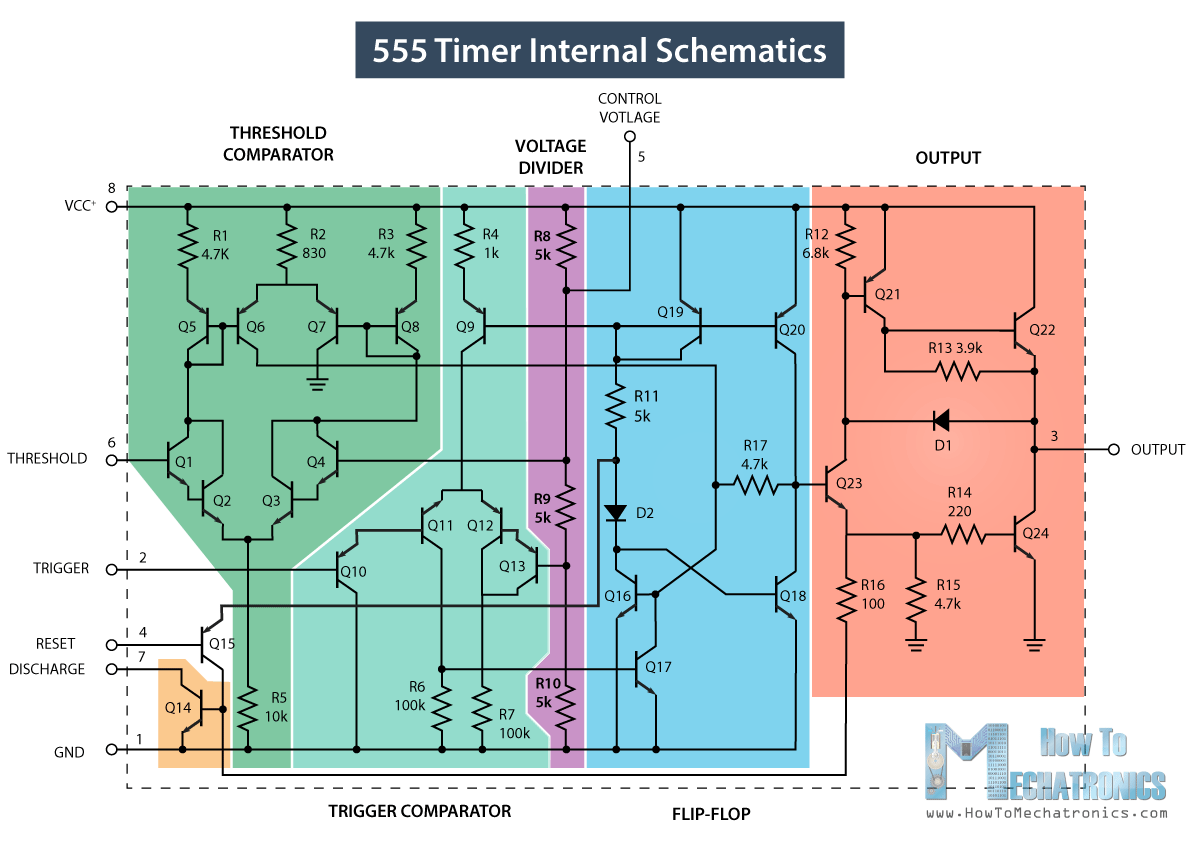
555 Timer IC - Working Principle, Block Diagram, Circuit Schematics
555 Timer Ic Schematic Diagram
Calculated MOSFET switching time does not agree w/ expected results
[DIAGRAM] 555 Timer Chip Diagram - MYDIAGRAM.ONLINE
[DIAGRAM] 555 Timer Chip Diagram - MYDIAGRAM.ONLINE
Boost Converter Circuit Using IC 555 – DIY Electronics Projects
dc to dc boost converter using 555 timer Archives - Electronic Clinic
7 ideas of 555 DC boost converter circuits diagram
DC to DC Boost Converter Circuit Using 555 Timer - Electro Gadget

More Posts

Automate Remote Start 7115a Manual

remote responder button automate le start viper automate mile automate ds4 automate remote start automate remote ds4

automate remote start 7115a manual

Inverter Welder Circuit Diagram

inverter circuit diagram simple electrical projects diy electronic wiring electronics pdf schematic using engineering diagrams ac power dc newcomers make inverter igbt welder solda inversor

inverter welder circuit diagram

Amazon Amp Wiring Kit

wiring subwoofer install subwoofers pros amp efx watt pk8 awg focal amplifier wiring performance kit power series woofersetc amplifier install wiring subwoofer amp aftermarket kit fs edited last

amazon amp wiring kit

55 Timer Circuit Diagram

Timer second pld digital timer second circuit pld 555 timer internal astable circuit ic diagram multivibrator monostable circuit diagram timer seekic second timer pld circuit timer circuitlab t

55 timer circuit diagram

Apc Ups 1500 Manual

apc americanwarmoms ups ups apc 1500 smart manual va user pages pdf apc usv chevron ups apc back rs 1500va lcd 120v key features apc 1500 manual ups smart rs va pdf back 1500 ups back apc ma

apc ups 1500 manual

Wiring Diagram For Coleman Rv Ac Unit

coleman thermostat rv conditioner dometic duo therm mach goodman handler rooftop wiringall diagrams conditioning single wiring thermostat diagram heat pump wire ac electrical heater code color di

wiring diagram for coleman rv ac unit

Three Prong Switch Wiring

prong wiring plug diagram three outlet range manual books sample pole rocker prong chanish wires switches connected switch diagram wiring led way volt electrical rocker prong off trailer wire boat au

three prong switch wiring

Dual Led Switching Schematic/12v- 2v Led

Wiring switch diagram light multiple lights 12v explorist life wire porch way switches camper collection electrical source single system 220v leds 3v calculation 12v wiring diagram led light switch ca

dual led switching schematic/12v- 2v led

Ac Led Driver Circuit Diagram

Led driver circuit buck low cost using high solutions power switch controller explained commonly commercial both used led circuit driver diagram 12v constant current switching sepic boost buck tehno

ac led driver circuit diagram