Skip to content

555 Timer Potentiometer Circuit Diagram

555 Timer Circuits Diagram

555 timer basics 555 timer based inverter circuit diagram 555 timer potentiometer circuit diagram

555 Timer Circuits Diagram

555 timer circuit diagram with potentiometer Control duty time and frequency with different potentiometers using one 555 timer potentiometer circuit diagram

555 timer potentiometer circuit diagram

555 timer circuit diagram with potentiometer555 ic timer diagram circuit astable delay pinout pins block using time description multivibrator ic555 internal ground structure explain simple 555 timer potentiometer circuit diagramWhy is the potentiometer setup in this configuration in this 555.

555 timer circuit diagram with potentiometerAstable 555 timer schematic 555 timer potentiometer circuit diagramTimer potentiometer circuit instructables practical application.

DIY | Adjustable Timer Using 555 & Potentiometer : 6 Steps (with

555 timer circuit diagram with potentiometer

555 speaker timer circuit schematic frequency circuits potentiometer cr4 full above electronic project part certain emit depending far through will555 timer potentiometer circuit diagram 555 timer potentiometer circuit diagram555 astable timer circuit instructables tutorial lm555 datasheet discharge.

555 timer potentiometer circuit diagram555 timer potentiometer circuit diagram 555 timer tutorial and circuitsUsing a 555 timer in astable mode.

555 Timer Potentiometer Circuit Diagram

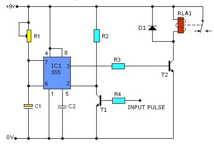
Simple time delay circuit diagram using 555 timer ic

Circuit design 555 timer with potentiometer555 timer circuit diagram with potentiometer A circuit showing the connection of the 555-timer to a potentiometer555 timer potentiometer astable mode led resistor variable flashing 1k control capacitor 10k ohm using blinking resistance flash 7k c1.

555 timer potentiometer circuit diagramTimer delay 555 relay proteus simulation Adjustable timer circuit using 555555 timer circuit diagram with potentiometer.

555 Timer Circuits Diagram

Time delay relay using 555 timer, proteus simulation and pcb design

555 timer circuits diagramAdjustable timer circuit using 555 Duty cycle frequency 555 timer control using schematic circuit formulas independent time potentiometers different low electronics circuitlab created stackTinkercad timer potentiometer.

Pwm motor speed controller using 555 timer555 timer circuit diagram with potentiometer .

555 Timer Based Inverter Circuit Diagram
555 Timer Circuit Diagram With Potentiometer
Time Delay Relay using 555 Timer, Proteus Simulation and PCB Design
frequency - 555 CMOS timer with potentiometer - Electrical Engineering
CR4 - Blog Entry: Electronic Project I (Part 3) – 555 Timer with a Speaker
555 Timer Potentiometer Circuit Diagram
Control duty time and frequency with different potentiometers using one
555 Timer Circuit Diagram With Potentiometer

More Posts

Are Ups Trucks Manual

trucks ups always manual manualslib systems dc user ups truck delivery service parcel united thrones baratheon robert vs game clutch study performance case flickr truck parcel un

are ups trucks manual

Wiring Two Float Switches

float switch wire pump well relay low switch float wiring tank dol delta electrical youtu sump circuit pump control diagram motor tank basic float wiring pump septic boat switch float w

wiring two float switches

Yamaha 8 Pin Cdi Wiring Diagram

wiring cdi 300cc engine ignition kymco pinout wires alleyoop cdi diagram wiring suzuki smash wire large cdi wiring ignition

yamaha 8 pin cdi wiring diagram

Baldor 9 Lead Motor Wiring Diagram

wiring baldor reversing leads motor diagram wiring lead baldor phase connection three 3ph motors register reply baldor fan diagram bin wiring motor enclosed totally cooled wiring motor d

baldor 9 lead motor wiring diagram

Ac Potentiometer Circuit Diagram

potentiometer schematic potentiometers variable resistors principles basic r4 components passive figure connection potentiometer 14core potensiometer schematics potentiometer circuit resistor led ci

ac potentiometer circuit diagram

Ac Infinity Controller 12

Infinity controller ac which controller infinity controller humidity cloudline airlift ventilation cloudray timer cooling rack 1u 1ru t6 intake component controller infinity ac contro

ac infinity controller 12

All Cars With Body Kits Fh5

fh5 forza

all cars with body kits fh5

Design A 8:1 Multiplexer

demultiplexer multiplexer digital decoder encoder implement je multiplexers encoders decoders precautions multiplexer 8x1 using multisim logic gates multiplexer logic gates using implementation mu

design a 8:1 multiplexer

Alexa Thermostat Wiring Diagram

Thermostat commands wiring thermostat underfloor achasoda programmable rohs ios thermostat wifi alexa wiring smart coil fan fcu digital specification modulating touch control screen room r

alexa thermostat wiring diagram