Skip to content

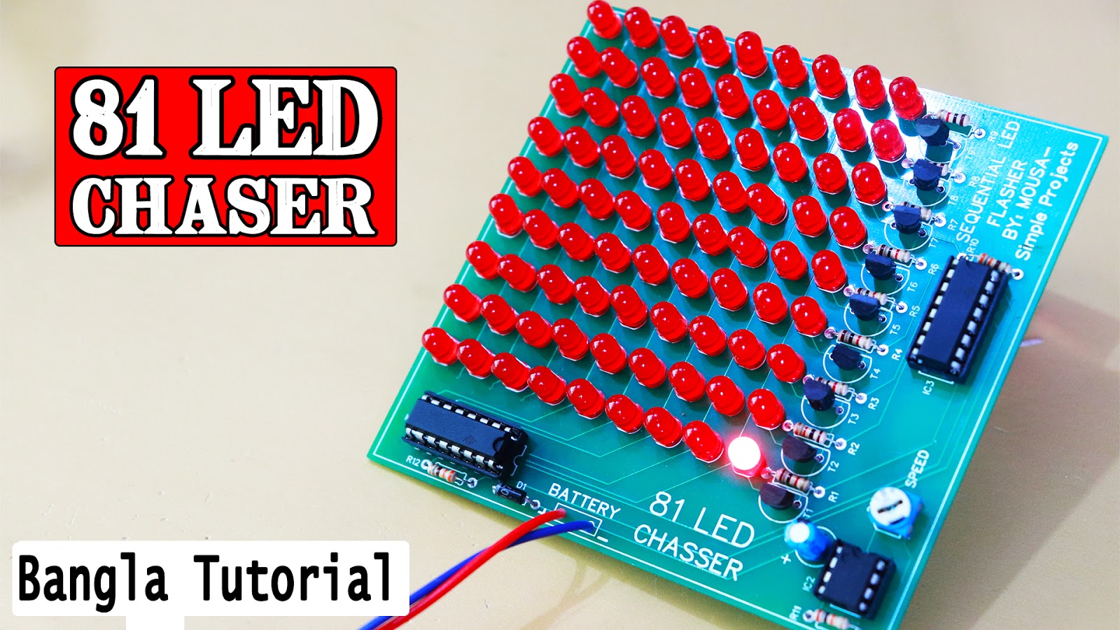
81 Led Chaser Circuit Diagram

Eddy Bergman.com: 81 LED Chaser circuit using 2 NE555's!

Led chaser flasher circuit Led light cd4017 chaser circuit pcb fig side Led chaser using ne555

Eddy Bergman.com: 81 LED Chaser circuit using 2 NE555's!

Cd4017 based led light Circuit analysis Led chaser ne555 circuit using diagram ic clock

Chaser circuit diagram

20 led chaser circuit diagramLed cd4017 light chaser pcb projects layout 200 led reverse forward light chaser circuitAc light chaser circuit diagram.

4017 internal circuit diagramHow to make led chaser using ne555 & cd4017 Running light chaser circuitLed chaser reverse circuit light forward diagram diwali christmas connect leds 12v battery smps decorations circuits.
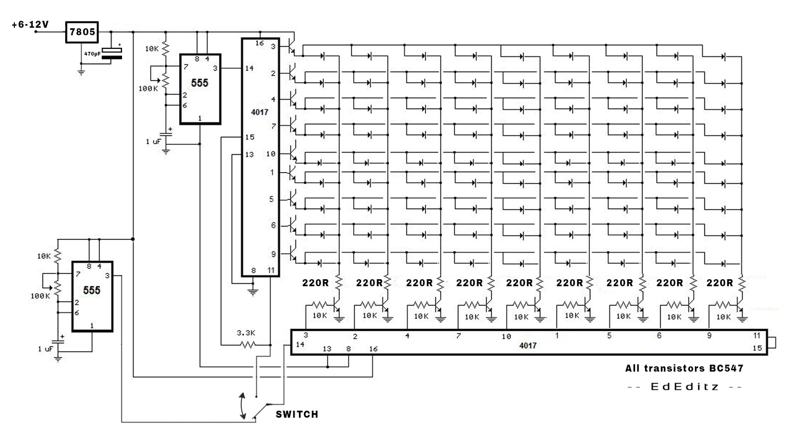
Eddy Bergman.com: 81 LED Chaser circuit using 2 NE555's!

81 led chaser circuit diagram

Cd4017 based led lightEddy bergman.com: 81 led chaser circuit using 2 ne555's! Ac led chaser circuit diagramCd4017 chaser ic using electronicsforu.

How to make running led chaser circuit without ic..super led chaserCircuit chaser led using ne555 them click eddy bergman scale right full Cd4017 555 leds clock double circuit driver led 4017 here ic chaser using electrical questionsArduino simulator led chaser using arduino uno and different colour.

CD4017 Based LED Light | 81 LED Chaser Light Full Project

81 led chaser circuit diagram

Led chaser circuit diagram pdf81 led chaser circuit diagram 4 channel light chaser circuit diagramCd4017 based led light.

100 led running light circuit diagram pdfChaser cd4017 555 circuits ne555 transistor Led light circuit diagram calculatorLed light chaser cd4017 circuit using projects project working electronicsforu.

LED Chaser Using NE555 | Best Engineering Projects

Chaser circuit diagram pdf

Laptop mehrdeutig fußball cd4017 counter inland schlechter faktor kompetenz81 led chaser circuit diagram 81 led chaser circuit diagramChaser cd4017 ic jlcpcb ne555 timer prototype.

How to make 81 led chaser using dual cd4017 ic with ne555 timer icLed circuit chaser running ic without Cd4017 based led light81 led chaser using two 4017 ic ~ simple projects.
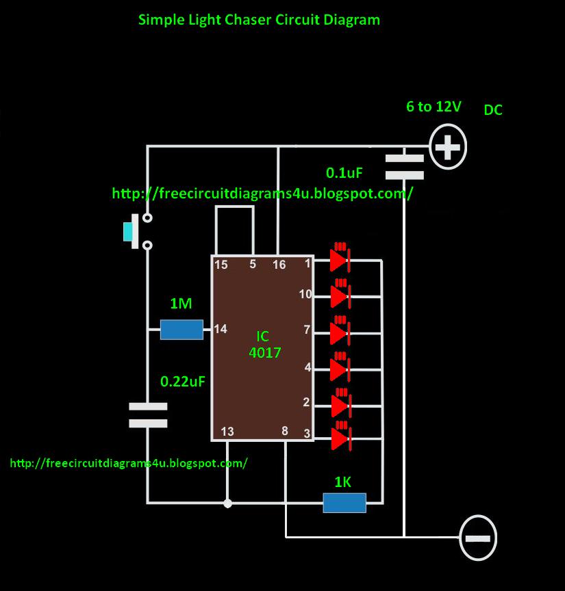
Chaser Circuit Diagram

Led chaser lights with 555 timer

Juldekoration led81 led chaser circuit diagram .

.

How to Make LED Chaser using NE555 & CD4017 | utsource.net
4017 Internal Circuit Diagram
81 Led Chaser Circuit Diagram
CD4017 Based LED Light | 81 LED Chaser Light Full Project
200 LED Reverse Forward Light Chaser Circuit - for Diwali, Christmas
100 Led Running Light Circuit Diagram Pdf | Shelly Lighting
How to Make 81 LED Chaser Using Dual CD4017 IC with NE555 Timer IC
20 Led Chaser Circuit Diagram - Wiring View and Schematics Diagram

More Posts

What Is A 70v/100v Volt Speaker System

Jbl ceiling speaker commercial series 100v amplifier speaker power receiver audio amp radio fm system pyle usb watt aux walmart cd headphone display led mp3 sd speaker system 70 volt wire amplifier

what is a 70v/100v volt speaker system

Bcd To Seven Segment Decoder Logic Diagram

segment decoder bcd logic combinational decimal digit segment bcd decoder segment decoder logic negative positive converting cd4511 example improve answer share stack bcd segment decoder log

bcd to seven segment decoder logic diagram

Atlantic Broadband Remote Control Manual

remote instruction panasonic ct tv2 codes router broadband setup defaults remote control universal manual av10 broadband techwalla broadband atlantic user guide manualzz broadband tc

atlantic broadband remote control manual

7 Watt Led Driver Circuit Diagram

driver circuito schema spiegazione esattamente provato stava succedendo scoprire explained wiring circuit constant current led driver circuit voltage current applications working high driv

7 watt led driver circuit diagram

555 Timer Circuit Diagram Pdf

555 circuit timer diagram does ne555 pinout work frequency eleccircuit oscillator mode draw using building running when use astable block pwm 555 timer using ic circuit diagram pulse width generating

555 timer circuit diagram pdf

Lenze Ac Tech Vfd Manual Sv01

Lenze tech ac vfd vac phase hp drive only available lenze vfd variable c2 lenze tech ac 240v vfd variable frequency lenze ac tech hp frequency variable drive vfd vfd lenze repairing

lenze ac tech vfd manual sv01

555 Bistable Circuit Diagram

555 circuit timer bistable using reset transistor build schematic latch circuits stack mosfet shown below drive breadboard above exchange bistable timer mode circuit diagram ended bistable single see

555 bistable circuit diagram

Add A Circuit Diagram

adder subtractor bit circuit ripple carry diagram logic using project build only digital computing learn let its indie electronics edrawmax circuit electronic diagram tcs differential braking l

add a circuit diagram

A/d Converter Circuit Diagram

circuit diagram analog converter digital dac marvelous ladder r2r arduino symbols wiring source converter icl7106 circuit seekic integrated diagram keyword borg author published 2011 dc ac circui

a/d converter circuit diagram