Skip to content

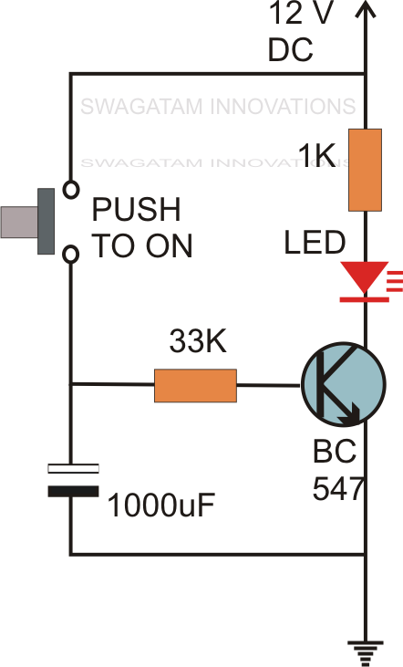
Delay Circuit Using 555

555 Delay Circuit Diagram

Delay timer adjustable circuit off 555 schematic ic using auto explanation works Delay circuit using 555 timer Off delay timer circuit using 555

555 Delay Circuit Diagram

Timer delay 555 circuit off using ic auto simple schematic adjustable module relay output dc inline loads appliances heavy ac Delay circuit 555 timer time using electronics electronic pulse project ic circuits help schematic turn capacitor will if gif amperage Ic 555 delay timer circuit

How to build a delay before turn on circuit with a 555 timer

Time delay relay circuit using 555 timer ic555 delay circuit timer turn before using mosfet ic reset schematic transistor build breadboard circuits output get stack learningaboutelectronics drive Delay timer 555 power circuit onlineCircuit 555 delay timer.

Electronic timer using scr circuit diagramTime delay circuit with relay 555 delay off timer circuit for delay before turn off circuitTime delay circuit using 555 timer.

How to Build a Delay Before Turn On Circuit with a 555 Timer

Circuit switching delay diagram

On delay timer : 네이버 블로그Time delay relay circuit using 555 timer ic share project, 43% off Time delay circuit diagramSimple time delay circuit using 555 timer.

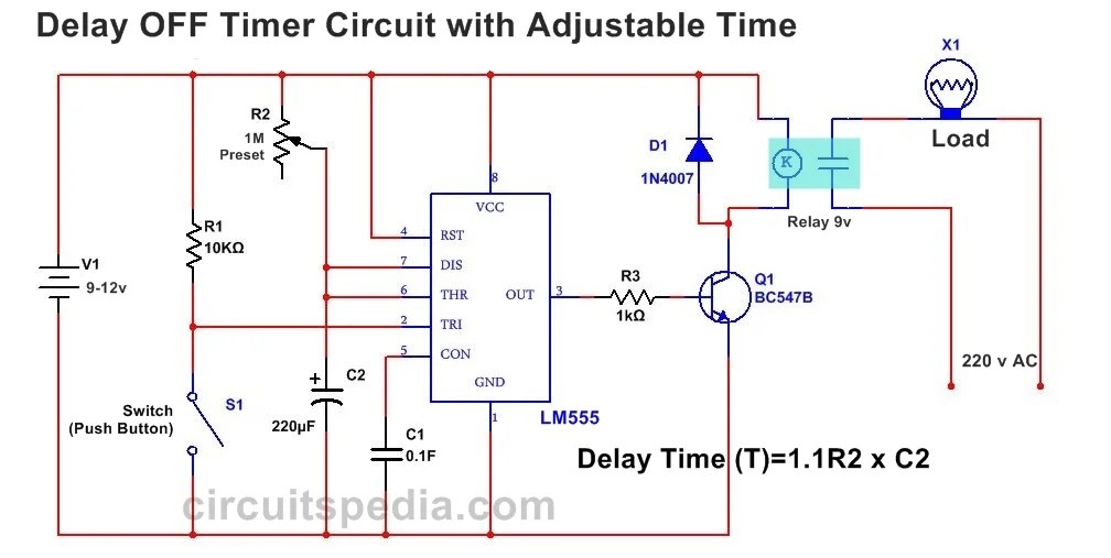
Adjustable auto on off delay timer circuit using 555 icVerständnisfrage zu einschaltzerzögerung mit ne555 On delay timer circuitHow to build a delay before turn off circuit with a 555 timer.

Timer With On-Off Delay | Electronic Circuits

555 delay circuit diagram

Circuit delay 555 timer ic off time counterOff delay timer circuit diagram Circuit off delay timer 555 turn before schematic shown below breadboard aboveIc 555 delay timer circuit.

Adjustable auto on off delay timer circuit using 555 ic555 timer delay on circuit diagram 555 timer delay off circuit diagramOff-delay timer circuit using 555 ic.

Electronic Timer Using Scr Circuit Diagram

Time delay circuit diagram

Delay timer circuit switch diagram power time electronic load projects duration artigoPower-on delay with 555 timer Delay circuit timer time 555 simple using circuits ic 5v diy power switching relay hasDelay timer circuit off 555 diagram switch time power turn circuits before given.

Timer with on-off delayTimer circuit delay off 555 circuits using ic ne time electronic counter common here designed 555 delay timer circuit off diagram simple time switch circuits using timers make application display voltage electronics lamp choose board.

Time Delay Circuit Diagram
555 Delay Circuit Diagram
555 Delay OFF Timer Circuit For Delay Before Turn OFF Circuit
Time Delay Relay Circuit Using 555 Timer IC Share Project, 43% OFF
Simple Time Delay Circuit using 555 Timer
Off-Delay Timer Circuit using 555 IC - Electronics Area
Time Delay Circuit with Relay
555 Timer Delay Off Circuit Diagram - EEWeb
off delay timer circuit diagram

More Posts

C10 Vent Window Frame

vent c10 window rubber 1972 1967 chevy window vent chevy c10 1967 1972 replace rubber remove vent window c10 repair squarebody vent window c10 side vintage parts 1963 assembly chevy

c10 vent window frame

How Many Watts Does A Ups Use

Watts many power does computer need supply inverter wattage watt requirements buying cpi abord ceci devez acheter lire prendre much evaluate watts appliances electric contribute

how many watts does a ups use

700r4 Transmission Wiring Diagram No Computer

wiring diagram 700r4 transmission lock th350 lockup 4r 200 switch non instructions carburetor th 700 r4 1984 wires controlled vacuum 700r4 lockup 200r4 4r harness th350 700r4 wiring diagram t

700r4 transmission wiring diagram no computer

Abu Garcia Max Lp Dlc Left

Baitcast abu reel combo lp abu reel baitcast baitcaster baitcaster abu combo anaconda combos shimano abu casting reel combo baitcast 6ft 6in maxpro combos 1pc tackledirect abu reel handed baitcast

abu garcia max lp dlc left

Ac Cdi Input Power

cdi dc ac operated battery cdi cdi ac 110cc 6p kart 150cc 250cc 125cc taotao sunl atv 200cc bike box go cdi cdi unit ac digital ec21 cdi ac epoxy cdi circuit wiringg holley inputs outp

ac cdi input power

Blower Motor Wiring Diagram Manual

blower motor wiring diagram manual blower resistor samarins accord reliable blower manual ww2 justanswer blower motor kia spectra sportage heater resistor blower wiring f150 justans

blower motor wiring diagram manual

Design A 3:8 Decoder Circuit Using Gates

Decoder vhdl encoder using 3x8 8x3 ckt write engineersgarage decoder using decoders only logic three implementation digital do stack adder decoder full combinational gate htm active de

design a 3:8 decoder circuit using gates

Allen Bradley Powerflex 70 Manual

powerflex bradley 480vac vfd variable allen hp speed drive title item powerflex bradley allen vfd 15hp wty 18mo title item powerflex bradley rockwell drives variable pow

allen bradley powerflex 70 manual

Aby Circuit Diagram

poe 3bt ieee ethernet controller interface rectifiers aby bigshot amps two combining switch radial tuner aby switch circuit diy ab guitar morley may buffer klon dual pcb effects here few b

aby circuit diagram