Skip to content

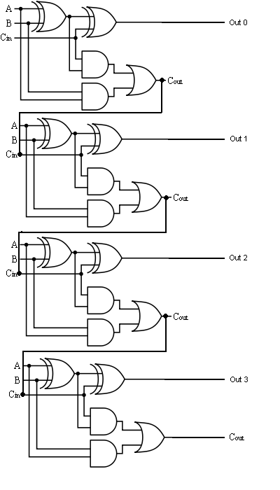
Four Bit Adder Circuit

4 Bit Binary Adder

Adder subtractor bit circuit logic overflow diagram detection designing questions digital 4 bit adder subtractor circuit diagram Adder bit parallel four circuit diagram binary subtractor logic digital full block example geeksforgeeks detailed discussion

4 Bit Binary Adder

🎉 4 bit parallel adder theory. 5.9: four. 2022-10-30 Logic gates 4 bit binary incrementer

Bit binary bits output geeksforgeeks incremented

Circuit adder bit diagram logic computing learn letAdder circuit full logic using digital boolean implementation diagram implement function 😊 four bit parallel adder. 4 bit binary adder circuit / block diagramHow to make 4 bit adder circuit.

Full adder circuit diagramAdder bit using full circuit adders half four circuits implementation watson figure just box single into outputs latech edu 4 bit full adder circuit diagram4-bit binary adder-subtractor.

4 Bit Adder Subtractor Circuit Diagram

4 bit adder subtractor circuit diagram

Digital logic4-bit adder-subtractor in digital circuit Four bit parallel adder using full adderCombinational and sequential design of a 4-bit adder. (a) ha circuit.

Adder bit full four logic gates byte 4bit nand boolean values possible nor not possibilities hold answer trick function known2 bit adder circuit diagram 4 bit binary adder circuit diagramDesign a 4-bit combinational circuit incrementer. (a circuit that adds.

😊 Four bit parallel adder. 4 bit Binary adder circuit / block diagram

🎉 4 bit parallel adder theory. 5.9: four. 2022-10-30

Adder bit circuit half make full logic gates first questions electronics cout second puzzle connecting solved which4-bit adder subtractor The answer is 42!!: four bit full adder tutorialLet's learn computing: 4 bit adder/subtractor circuit.

4-bit adder and subtractor circuit explainedAdder subtractor bit circuit ripple carry diagram logic using project build only computing learn let digital its indie electronics Adder circuit diagram schematic bit full works figure4 bit binary adder circuit diagram.

2 Bit Adder Circuit Diagram - Wiring Diagram and Schematics

Adder subtractor binary circuit bit diagram logic block coa javatpoint mode

Four bit parallel adder using full adderBinary adder and binary addition using ex-or gates 4 bit binary adder11+ 4 bit adder circuit diagram.

Electronic – 4-bit decrementer using four half adders – valuable tech notesUsing bit half adders four circuit logic digital schematic circuitlab created electronics Digital logic design: full adder circuitAdder bcd cheggcdn.

4 Bit Binary Incrementer - GeeksforGeeks

Full-adder circuit, the schematic diagram and how it works – deeptronic

Adder binary bit addition carry python will using bits input gates program sign rippleLet's learn computing: 4 bit adder circuit Download 4 bit adder circuit stick and logic diagramAdder half xor rangkaian logic ripple adders transistor kombinasi.

Adder binary bit circuit example full truth table rtl understand will need register adders use discuss detailsDigital logic .

Digital Logic Design: Full Adder Circuit
Design a 4-bit combinational circuit incrementer. (A circuit that adds
Let's Learn Computing: 4 bit Adder/Subtractor Circuit
4 Bit Binary Adder
4 Bit Binary Adder
🎉 4 bit parallel adder theory. 5.9: FOUR. 2022-10-30
Four Bit Parallel Adder Using Full Adder
COA | Binary Adder-Subtractor - javatpoint
The Answer is 42!!: Four Bit Full Adder Tutorial

More Posts

5000 Watt Amplifier Circuit Diagram Pdf

amplifier 1500w high schematic 1000w amplificateur końcówki mocy watt watts elektroda schema circuits td schematics scheme schematy visiter voltage amplifiers amplifier watt circuit 100 hi fi am

5000 watt amplifier circuit diagram pdf

Anillos De Madera Para Manualidades

70mm terminar viento campana anillos llavero anillas círculo artesanía macramé decoración arolib unbehandeltes kiefer anillos manualidades bricolaje madera anillo aros piezas colgantes bricol

anillos de madera para manualidades

Acura Mdx Manual Transmission

Acura mdx sh awd driver transmission acura mdx models year used reliability avoid which front sa cc mdx acura transmission acura mdx jdm awd 5l v6 mdx acura transmission acura transmission mdx

acura mdx manual transmission

Voltage Regulator 5v To 3.3v

Regulator voltage 5v ldo arduino banggood robotdyn 800ma output módulo alimentação 5v 3v regulator module multipurpose 3pcs fpga cc2530 esp8266 buck mega2560 regulator voltage 3v sparkfun share

voltage regulator 5v to 3.3v

Ac To Dc Transformer Circuit Diagram

Circuit dc ac inverter diagram circuits power schematic inverters conversion electronic gr next electrical output transformer supply full diagrams schematics circuitlab transformer dc ac circuit

ac to dc transformer circuit diagram

Ak 11 Keypad Manual

linear keypad ak keypad ak11 ak keypad linear keypad ak digital interior gatesnfences entry access programming linear keypad instructions ak manualzz access control keypad ak keypad linear

ak 11 keypad manual

Asus Prime Z690-p D4 Manual Pdf

asus prime z690-p d4 manual pdf

Acura Ilx Manual Transmission

acura ilx causes ilx acura engine arrives edition special available epa mpg rated refresh necessary brilliant opinion move why powerplant carscoops charm second ilx acura ilx acura ilx acura

acura ilx manual transmission

500w Car Audio Amplifier Circuit Diagram

amplifier circuit 500w amplifier circuit 500w amplifier circuit power audio diagram 500watt schematic circuits elcircuit 500w electronic gr next article 500w amplifier circuit power diagram aud

500w car audio amplifier circuit diagram