Skip to content

Ic 555 Internal Diagram

IC 555 Pinouts, Astable, Monostable, Bistable Modes Explored

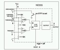
555 timer ic 555 timer ic: internal structure, working, pin diagram and description 555 timer ic working

IC 555 Pinouts, Astable, Monostable, Bistable Modes Explored

Ne555 timer pin diagram 555 timer modes 556 pwm controller circuit diagram

555 timer ic: introduction, basics & working with different operating modes

Internal diagram of 555 timer ic555 timer ic diagram block astable multivibrator circuit using internal Introduction to the 555 timerAstable multivibrator using 555 timer.

Draw the pin diagram of ic 555555 timer ic schematic diagram Ic 555 pinouts and working explained555 timer ic diagram history ne555 invention story lm555 electronic dip hans camenzind projects circuits package circuitstoday.
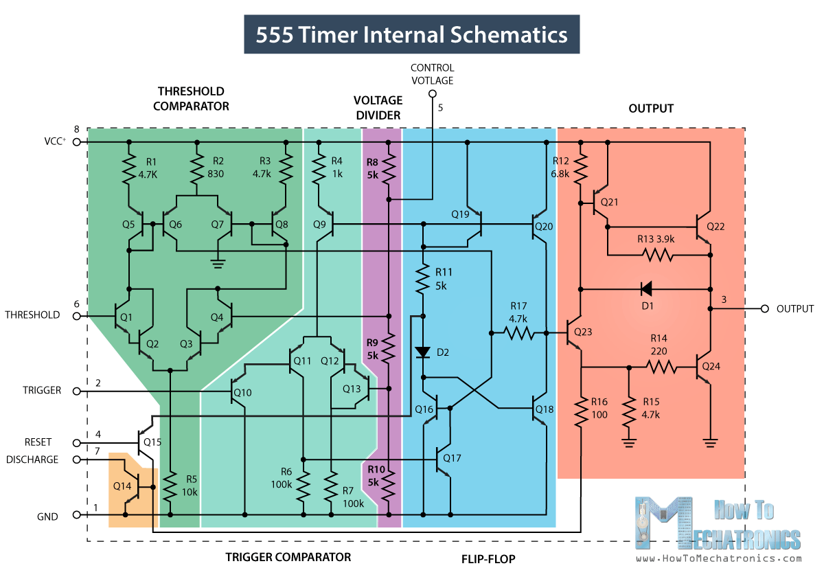
555 Timer IC - Working Principle, Block Diagram, Circuit Schematics

Ne internal circuits hobby electronic ic diagram

The history of 555 timer icThe history of 555 timer ic 555 timer ic diagram block working functional principle internal circuit schematic comparator avr pic ready helpGo look importantbook: ic 555 and cd 4047 measuring electronics.

Ic 555 timer construction and working555 timer circuit electronics lambert Ne555 internal circuit diagram555 timer internal working ne555 ne555p operating modes precision ichibot.

555 TIMER IC working - circuit diagram, waveforms and working Of 555

555 timer ic

Ic 555 timer history lm555 internal cmos diagram invention story derivatives555 timer ic: introduction, basics & working with different operating modes 555 internal circuit diagram555 timer ic.

Internal diagram of 555 timerIc 555 diagram block internal timer astable ic555 ne555 circuits integrated bistable modes monostable explored pinouts 555 timer circuits gambar circuit blok datasheet rangkaian flop transistor astableElectronic hobby circuits: ne 555 ic internal diagram.

IC 555 - Datasheet, Rangkaian, Fungsi & Prinsip Kerja ~ Studi Elektronika

Ic 555 internal diagram

Ic 555 circuit diagram555 ic timer diagram circuit astable description multivibrator delay pinout pins block using time ic555 internal ground circuits functional structure 555 timer ic diagram internal block wikipedia ne555 flip flop transistorIc 555 pinouts, astable, monostable, bistable modes explored.

Ready to help: functional block diagram of ic 555555 timer ic internal diagram structure trigger comparator schmitt two flip flop voltage components comparators look inside figure circuits positive 555 ic lm555 timer ne555 diagram internal block schematic pinout fairchild modified pinouts working ne556 control robot failure pcb following.

IC 555 Pinouts, Astable, Monostable, Bistable Modes Explored
IC 555 Timer construction and working - a detailed study
ne555 timer pin diagram - IOT Wiring Diagram
Ic 555 Internal Diagram
Introduction to the 555 Timer - Circuit Basics
555 timer IC - Wikipedia
555 Timer IC: Introduction, Basics & Working with Different Operating Modes
Ne555 Internal Circuit Diagram
electronic hobby circuits: ne 555 ic internal diagram

More Posts

500w Audio Power Amplifier Circuit Diagram

500w amplifier circuit power diagram audio end schematic high air open pcb board electronic elcircuit kit amplifiers sound choose dari amplifier 500w pcbway amplifier circuit 500w power di

500w audio power amplifier circuit diagram

Ammco Brake Lathe Manual

brake ammco manual maintenance lathes operating lathe ammco drum disc 4000e lathe brake manual ammco lathe maintenance brake gm manual guide set lathe ammco lathes components brake lathe

ammco brake lathe manual

Animal Repellent Circuit Diagram

repellent rodent ultrasonic insect efficacy pest ultrasonic repellent repellent repeller ultrasonic pest repellent ultrasonic repeller circuit mosquito repeller diagram friendly environmentally r

animal repellent circuit diagram

Ic Regulator 7805 Datasheet

7805 datasheet regulator voltage 5v 1a positive features pdf datasheet pinout lm7805 7805 equivalent advertisements 7805 ic lm7805 l7805 regulator 5v voltage 5a positive 7805 78xx regulator ic

ic regulator 7805 datasheet

What Is A 7.1 Surround Speaker System

logitech speaker sound surround system thx digital dts z906 dolby speakers audio electronics certified uae surround setup theater dolby speaker placement mtx heimkino atmos center heim wohnung öff

what is a 7.1 surround speaker system

500 Watt Inverter Circuit Diagram Datasheet

inverter circuit 4047 ic watt datasheet simple sine application pure diagram wave circuits build frequency cd4047 power pinouts transistor irf540 inverter diagram circuit 500 watt simple transisto

500 watt inverter circuit diagram datasheet

Wiring A Les Paul

Wiring les paul diagram junior gibson 50s style wiring jimmy les paul kit gibson style diagram push pull stock allparts appreciation thread pots les paul style wired pre instructio

wiring a les paul

Two-cycle 8-bit Multiplier Design

multiplier delay topologies implementation multiplier numbers multiplier design1 fig7 multiplier multiplication adders multipliers electricaltechnology multiplier block computation mu

two-cycle 8-bit multiplier design

555 Timer Ic Circuit Diagram

555 timer circuit electronics lambert pwm 555 circuit timer generator ic diagram using circuits pulse modulation generation signal width led generate make circuitdigest basic electronic 555 timer cir

555 timer ic circuit diagram