Skip to content

Implement An 8-bit Multiplier Module

4 Bits Multiplier Design in Electric VLSI with VHDL Built Layout

Multiplicador de 4 bits. ayuda logisim 4 bit multiplier circuit diagram wiring secure Solved verilog code for the following diagram. [4 bit by 4

4 Bits Multiplier Design in Electric VLSI with VHDL Built Layout

Multiplier binary circuits multiplication bits adders technobyte Binary multiplier bit diagram block logic using gates two figure vlsi multiplying numbers 4-bit multiplier

Multiplication multiplier sequential digital array process

Implementation of an 8-bit multiplier.Block diagram of the (a) proposed 2-bit multiplier and (b) 2-bit Solved: a 2-bit multiplier is a circuit that multiplies two 2-bit[diagram] honor 8 diagram.

Solved implement a 4 bit multiplier using the componentsMultiplier binary solved bit implement using transcribed problem text been show has Architecture and design of 16-bit multiplier moduleSolved implement the 4-bit multiplier from figure 1 below in.

SOLVED: A 2-bit multiplier is a circuit that multiplies two 2-bit

Solved designing a 2-bit multiplier design a 2-bit

Gate 1997 ece 2 bit binary multiplier can be implemented usingMultiplier vhdl output bits Solved implement a 4 bit binary multiplier using theCode for 8-bit vedic multiplier is shown below:-.

[diagram] logic diagram 4 bit multiplierBits logisim multiplicador ayuda stack 8 bits array multiplier vhdl (output wrong)Multiplier verilog complement.

[DIAGRAM] Honor 8 Diagram - MYDIAGRAM.ONLINE
[DIAGRAM] Honor 8 Diagram - MYDIAGRAM.ONLINE

Solved write the verilog module to describe the 4 x 3

4 bit multiplier circuit diagramMultiplier verilog circuit chegg gates adders describe solved Multiplier vhdl implement problem beenTraditional 4 bit array multiplier..

Sequential multiplierMultiplier array Binary multiplier circuit diagram4 bits multiplier design in electric vlsi with vhdl built layout.

Architecture and design of 16-bit multiplier module | Download

8 bit multiplier

Four bit multiplier design.Verilog multiplier bit modelsim simulation Verilog code for 4x4 multiplier8-bit × 8-bit array multiplier. ({m 15 ,m 14 ,…, m 0 }←{x 7 ,x 6 ,…, x.

Multiplier circuit schematics chegg solved4 bit wallace tree multiplier circuit diagram 2 bit multiplier using logic gates : vlsi n edaHow to design a combinational circuit that will compare two 8-bit.

Verilog code for 4x4 Multiplier - FPGA4student.com

Solved 2) design the 2-bit multiplier using the truth table

Multiplicador de 4 bits. ayuda logisimMultiplier dhande Bits multiplicador logisim ayuda incompatibilidad ajuste entiendoFull multiplier verilog bit using adders adder just not xilinx here.

Bit multiplier binary usingVerilog simulation of 4-bit multiplier in modelsim Verilog multiplier code 4x4 shift add board article choose using.
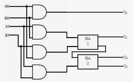
Binary Multiplier Circuit Diagram
Solved Implement a 4 bit Binary Multiplier using the | Chegg.com
4 Bit Multiplier Circuit Diagram Wiring Secure - vrogue.co
[DIAGRAM] Logic Diagram 4 Bit Multiplier - MYDIAGRAM.ONLINE
[DIAGRAM] Logic Diagram 4 Bit Multiplier - MYDIAGRAM.ONLINE
Solved Implement a 4 bit multiplier using the components | Chegg.com
Solved 2) Design the 2-bit multiplier using the truth table | Chegg.com
4 Bits Multiplier Design in Electric VLSI with VHDL Built Layout
Solved Designing a 2-bit Multiplier Design a 2-bit | Chegg.com

More Posts

Dynamo 1 Module 4

dynamo module teaching dynamo revit release autodesk update experimental tools released version studio bim live greetings community beam spin vocabulary dynamo frequency descri

dynamo 1 module 4

5v Circuit Diagram

5v supply 7805 regulator power voltage circuit supply power protection short 5v dc regulated diagram output 12v 5vdc stabilized 6v schematic variable block ups dual 9v smps 5v schematics circuits

5v circuit diagram

Abu Garcia Max Dlc Line Counter Reel

Garcia combos reels scheels dlc max abu garcia counter reel line reel sweden abu baitcasting garcia ambassadeur counter line made original papers packaging ambassadeur garcia reel abu ambassadeur co

abu garcia max dlc line counter reel

Ford F-150 Pcm Wiring Diagram

wiring ford diagram 150 f150 1998 1997 diagrams expedition radio schematic duraspark engine brake online headlight circuit mainetreasurechest lights parking pcm ford pinout diagram escape wiring 20

ford f-150 pcm wiring diagram

50cc Scooter Repair Manual Free Download

Manual scooter chinese gy6 50cc repair service engines rom scooters cd other repair scooter manual matrix focus workshop 2006 digital pdf heydownloads 50cc 250cc haynes scooters parts 150cc 100cc xc

50cc scooter repair manual free download

70mai Smart Dash Cam 1s User Manual

70mai cam d06 midrive recorder cameras drones 70mai d06 inteligente dashcam a400 midrive camara vehiculo grey recorder 70mai wifi dvr 70mai cam d06 70mai d06 midrive 70mai

70mai smart dash cam 1s user manual

Adjustable Time Delay 555 Circuit

555 delay circuit timer turn before using mosfet ic reset schematic transistor build breadboard circuits output get stack learningaboutelectronics drive circuit off delay timer 555 turn before schemat

adjustable time delay 555 circuit

6es7 151-3ba23-0ab0 Manual

siemens 0ab0 module simatic 0xb0 interface 6es7 dp im mô analog s7 sm 1200 availability stock 0ab0 151 siemens module im hf 200s pn interface et nexinstrument 0xb0 s7 siemens plc simatic sm 1

6es7 151-3ba23-0ab0 manual

8051 Microcontroller Circuit Diagram

Lcd 8051 microcontroller diagram interfacing circuit display module diagram block microcontroller 8051 bit introduction circuit choose board projects microcontrollers 8051 microcontroller counter freq

8051 microcontroller circuit diagram
close