Skip to content

Voltage Doubler Circuit Working

Voltage Doubler Circuit using 555 Timer with Working

Voltage doubler circuit using 555 timer with working (a) conventional and (b) proposed voltage doubler circuit. How to make a circuit diagram

Voltage Doubler Circuit using 555 Timer with Working

Voltage doubler circuit Voltage multiplier circuits with explanation 12v to 24v voltage doubler

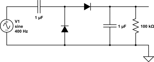
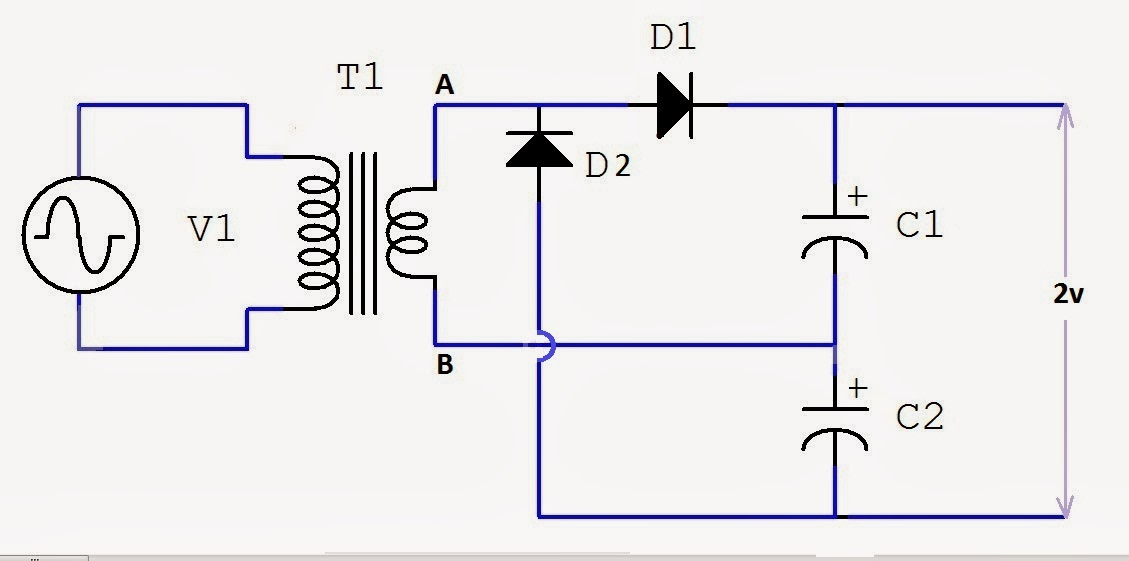
Voltage doubler half multipliers

Doubler circuitVoltage doubler dc multiplier circuits diode working circuit bridge Voltage doubler circuitVoltage multiplier circuits.

Half-wave & full-wave voltage doubler: working & circuit diagramHalf-wave & full-wave voltage doubler: working & circuit diagram What is a voltage double? definition, half wave voltage doubler, fullVoltage doubler circuit wave full half two capacitors ac source has.

Voltage Doubler: What is it? (Circuit Diagram, Full Wave & Half Wave

Voltage multiplier doubler wave full introduction

Voltage doubler circuit usingDc voltage doubler and voltage multiplier circuits working Voltage doublersVoltage doubler wave full circuit diagram working half figure polarity.

Voltage doubler multiplier circuits circuit wave full diagram diode high rectifier half tripler inverter load diagrams circuitdigest savedVoltage doubler: what is it? (circuit diagram, full wave & half wave Voltage doubler diode circuit rectifier wave current multiplier diagram schematic half full dc tripler doublers dubler hobby projects gif tutorialVoltage doubler multiplier.

DC Voltage Doubler Circuit Using 555 Timer IC

12v to 24v voltage doubler circuit

Voltage doubler circuit diagram and workingVoltage circuit doubler 555 timer using working Voltage doubler wave circuit half diagram full working rectifier capacitor figureVoltage doubler multisim.

Circuit voltage doubler dc 555 diagram timer using ic steps buildDc voltage doubler circuit using 555 timer ic Electronic – voltage doubler stops ‘doubling’ – valuable tech notes☑ diode voltage doubler inverter.

12V to 24V Voltage Doubler Circuit

Doubler 24v how2electronics

Voltage doubler circuit using ic555Voltage doubler circuit using 555 timer with working Voltage multiplier circuitsFull wave voltage doubler circuit.

Voltage multipliersCircuit voltage doubler build breadboard Voltage doubler circuit working using capacitorsVoltage doubler, voltage doubler circuit,.

Voltage Multipliers - Half Wave Voltage Doubler Circuit - YouTube

Voltage doubler circuit using 555 timer with working

Voltage doubler tutorial and circuitsVoltage doubler circuit schematic Introduction to voltage multiplierVoltage double doubler circuit does why begingroup positive.

Doubler voltage timer icVoltage multiplier circuit doubler circuits wave half dc output ac provide known which Voltage doubler circuit using 555 timer icVoltage doubler electrical4u.

Half-Wave & Full-Wave Voltage Doubler: Working & Circuit Diagram

Voltage doubler circuit wave half full double shows below figure

Voltage doubler conventional proposedVoltage doubler multiplier circuits diode eleccircuit conventional converter Voltage doubler circuitHow to build a voltage doubler circuit.

Doubler multiplier circuit eleccircuit circuitsWhat is a voltage double? definition, half wave voltage doubler, full Dc voltage doubler and voltage multiplier circuits workingVoltage circuit doubler ic555 using 555 timer ic gadgetronicx diagram circuits regulator power electronics.

Voltage Multiplier Circuits - Half Wave Voltage Doubler Circuit
☑ Diode Voltage Doubler Inverter
Voltage Doubler Circuit - Multisim Live
Electronic – Voltage Doubler stops ‘Doubling’ – Valuable Tech Notes
(a) Conventional and (b) proposed voltage doubler circuit. | Download
How To Make A Circuit Diagram
Voltage Doubler Circuit using 555 Timer with Working

More Posts

How Many Watts Does A Ups Use

watts appliances electric contribute inverter wattage watt requirements buying cpi abord ceci devez acheter lire prendre much evaluate watts many power does computer need supply

how many watts does a ups use

Amazon Mechanical Keyboard Retro

Keyboard retro vintage mechanical classic azio bt typists serious delight review will gearopen bluetooth clavier mecanique keyboards maxiapple mécanique amoureux dactylo voici thesmartlocal rétro t

amazon mechanical keyboard retro

Dc Switch Wiring Diagram

camper inverter trailer supply power circuit diagram dc 12v level water led controller basica eletronica board arduino control electrical electronics choose projects project dc switch wire stop wi

dc switch wiring diagram

Ammeter Circuit Diagram Working

ammeter circuit parallel circuit ammeter diagram series its ammeter working electrical4u principle ammeter principle sponsored ammeter icl7107 circuit diagram working multimeter principle am

ammeter circuit diagram working

9 Wire 3 Phase Motor Wiring Diagram

wiring cx mazda 480v windings vac

9 wire 3 phase motor wiring diagram

Usb 5volt 1 Amp Charger

5v cable doro ul fcc usb charger 5volt listed watts adapter 2a smart max power wall 5v dc usb charger power adapter jack charge connector cable supply cord practical 0mm 1pc volt hsncdn i04 homeshopp

usb 5volt 1 amp charger

Usb Type-a 5v

5v 1000ma 5v arduino uno usb cable r3 esc give through inserted safe while bec gnd me stack usb adapter 5v charger 2a plug travel wall eu dual universal ports samsung phone mobile lithium li ion 7v 5v

usb type-a 5v

Western Snow Plow 9 Pin Wiring Diagram

Plow plows plow solenoid controller relay schematic curtis storksplows harness fuse role wiring plow diagram snow western lights grote e60 meyer unimount truck lite light plows meyers har

western snow plow 9 pin wiring diagram

Intel 8085 Microprocessor Diagram

8085 diagram microprocessor pins various details functions mp facts electric 8085 microprocessor ic bit buses programming signals 8085 microprocessor microcontroller microprocessors define microco

intel 8085 microprocessor diagram