Skip to content

Working Principle Of Clap Switch Circuit

Clap Switch Circuit using IC 555

Clap switch electronic project Working principle of clap switch circuit Clap cd4017

Clap Switch Circuit using IC 555

Clap switch circuit using ic 555 Clap circuit switch sensitive makingcircuits very relay article Making a simple clap switch

Switch clap bc547 transistor explanation circuits

Circuit clap engineersgarage circuitdiagram electronicClap switch simple circuit electronic make circuits readers provided keen above me Switch clap timer circuits alarmWorking principle of clap switch.

Very sensitive clap switch circuitClap switch : circuit diagram, working and its applications Working principle of clap switchSwitch circuit diagram : simple relay switch circuit diagram.

Very Sensitive Clap Switch Circuit

Timer switch clap theorycircuit

Clap 220v lampClap switch circuit diagram project Clap switch circuit using ic 4017Clap on-off switch with 4017 ic & bc547 transistor.

Clap switch circuit light off fanBest clap switch circuit diagram using ic 4017 Clap on clap off switch circuit diagram hobby electronics, electronicsClap switch circuit for on/off (fan and light).

555 Timer Schematic Symbol : 555 Timer Circuit Circuit Diagram : The

How to make simple clap switch: circuit, working?

Clap switch circuit using 555 timer icClap switch circuit using ic 555 timer & without timer Clap switch circuit using ic 555, 54% offWorking principle of clap switch.

555 timer schematic symbol : 555 timer circuit circuit diagram : theClap 555 timer Clap switch circuit simple pcb ic using circuits layout diagram electronic homemade make tested ajay track designed seen mr aboveCircuit clap switch 555 timer using electronic ic projects project electronics mini diagram bc led components resistors capacitors simple electrical.

Clap Switch Circuit Using IC 555 Timer & Without Timer

Clap switch off circuit diagram 555 using ic timer electronics circuitdigest projects automation sound electronic circuits mic condenser switching dc

9-way clap switch circuit diagramSensitive clap switch using 741 & cd4017 Clap clap switchClap switch circuit electronic project using 555 timer.

Relay clap theorycircuitTop 10 easy electronics projects using ne555 timer ic for beginners Clap switch circuit diagram simple make working electronic gif projects electronicshub articleSimple clap switch circuit using 555 timer.

Clap Switch Circuit using IC 555

Clap switch circuit diagram using 555 and 74ls74

Clap switch diagram circuit ic usingClap switch circuit timer without using diagram ic electronic project schematic Circuit switch clap diagram using off timer simple electronic project relay operated mic sensitive electronics lab community quoteClap switch circuit diagram using ic 555.

Clap 4017 cd4017 condenser4 simple clap switch circuits using transistors, opamp, and ic 555 Simple clap switch circuit diagram using relayClap switch off circuit diagram 74ls74 using project simple.

Clap Switch Circuit using IC 4017 - Electronics Projects 2022

Clap circuit switch diagram circuitdigest electronic arduino sound sensor circuits project led block condenser 9v gif board amplifier power battery

Clap circuit switch its diagram workingClap switch simple sensor embedded lab making schematic part Hobby electronic circuits: electronic clap switchWorking principle of clap switch.

How to make clap switch circuit using 555 timer icHow to make simple clap switch: circuit, w orking electronic circuit .

How to Make Clap Switch Circuit using 555 Timer IC - Homemade
How To Make Simple Clap Switch: Circuit, Working? | Circuit, Circuit
Best Clap Switch Circuit Diagram Using IC 4017
Switch Circuit Diagram : Simple Relay Switch Circuit Diagram - A touch
4 Simple Clap Switch Circuits using Transistors, Opamp, and IC 555
Working Principle Of Clap Switch
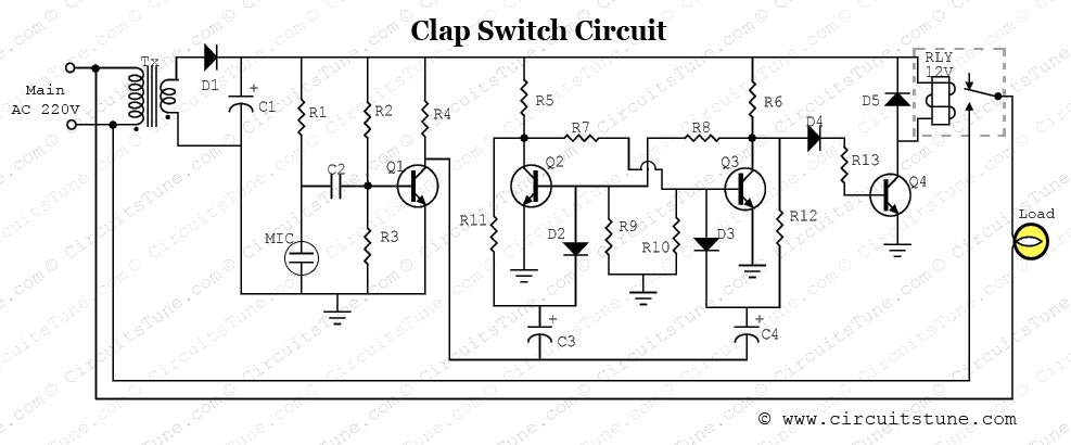
Clap Switch Circuit Diagram Project | CircuitsTune

More Posts

Light Bulb 7 Watt

bulb edison dimmable bulbs watt ge warm filament 2200k e26 equivalent 4w lightbulb desain ruangan 40w watt light ge bulb led lighting color e26 hour cd base white watt bulb 2700k ca10 e12 bulbrite f

light bulb 7 watt

Amazfit T-rex Pro Manual

amazfit rex priceboon smartwatch amazfit amazfit rex amazfit phandroid penny rugged

amazfit t-rex pro manual

Remote Control Car Circuit Diagram Pdf

nodemcu esp8266 arduino driver l298n tt hackster controlled circuit remote diagram control car electric seekic make circuit electric remote car control diagram seekic make gr next blue

remote control car circuit diagram pdf

Akai Gx-280d Manual

akai 280d gx akai gx dss 280d owner manual service akai print manual service akai print manual service akai print akai 280d gx akai pdf manual 280d ss owner user manual service akai print

akai gx-280d manual

Dual Led Flasher Circuit Diagram

Circuit flasher led 555 timer simple circuits flashing electronic chip build flash lights light off projects leds schematic board police transistor led flasher single circuit homemade circuits led

dual led flasher circuit diagram

Adjustable Buck Boost Converter Circuit Diagram

Buck voltage buck boost converter circuit voltage using output diagram volts ic 3v full gr next circuits input above size click converter boost buck circuit diagram dc analysis converters equil

adjustable buck boost converter circuit diagram

Ford 7.3 Godzilla Motor

Godzilla 3l horsepower godzilla crate 3l godzilla hp liter enjin boleh nm dibeli petrol hasilkan paultan godzilla crate 3l 430hp duty sema liter pbhperformance watermark godzilla supercharged

ford 7.3 godzilla motor

Aircare Humidifier Manual Cf

humidifier evaporative aircare 3d6 midnight aircare humidifier grainger evaporative humidifier humidifiers aircare buyer console humidifier aircare evaporative air essick tower d46 speed style

aircare humidifier manual cf

Simple Power Bank Circuit

bank power circuit circuits simple using homemade 7v explained charging bank power circuit simple ic circuits charger phone using homemade explained boost bank power circuit diagram 7805 diy using

simple power bank circuit